I haven’t posted much in the way of ‘how-to’ with the van because it is all well documented on the internet by plenty of #vanlifers and others. Ultimately I’m interested in enjoying the van on climbing and skiing trips not writing about it—a sentiment reinforced by the hours I’ve spent writing and organizing this post. However, a couple months ago I started researching how to install a heater in the van. This is a heater for when the vehicle is not running, but that uses the vehicle’s fuel tank for the fuel to generate heat. While there is some information out there on the install process, I did not find as much information as I’d hoped, particularly for the most difficult/scary portion of the install: getting a fuel line from the fuel tank on our van, a 2014 Chevy Express AWD.
Background
First a little background info on these heaters. There are two well known name brands which make gasoline & diesel heaters for vans, RVs, and construction equipment, Espar and Webasto. There are other brands out of Asia, but I did not entertain them as an option. I wanted to go with a well established company with a long history making these heaters and ruled out the off-brands—though they are considerably less expensive than the German ones.
As for why this versus a propane heater or something else, there’s plenty of sites out there extolling the virtues of this style heater so I’ll skip it here. The main reasons for me are simplicity in fuel management and dry heat inside the van.
As far as I can see Espar has a pretty good North American distribution with dealers located around the country, including at least one in Salt Lake. Webasto does not have this distribution network and indeed almost no representation in North America that I could find. Both companies make diesel and gasoline heaters. However, Espar’s gasoline model, Airtronic B4, is much larger than Webasto’s smallest unit, Air Top 2000 STC. The heat output capacity of the Espar is about double, which is way oversized for a Sprinter, Promaster, and Connect, let alone an Express. So if you have a gas engine then the Webasto Air Top 2000 STC is the only option for you, if ignoring cheap brands.
Picking a Mounting Location
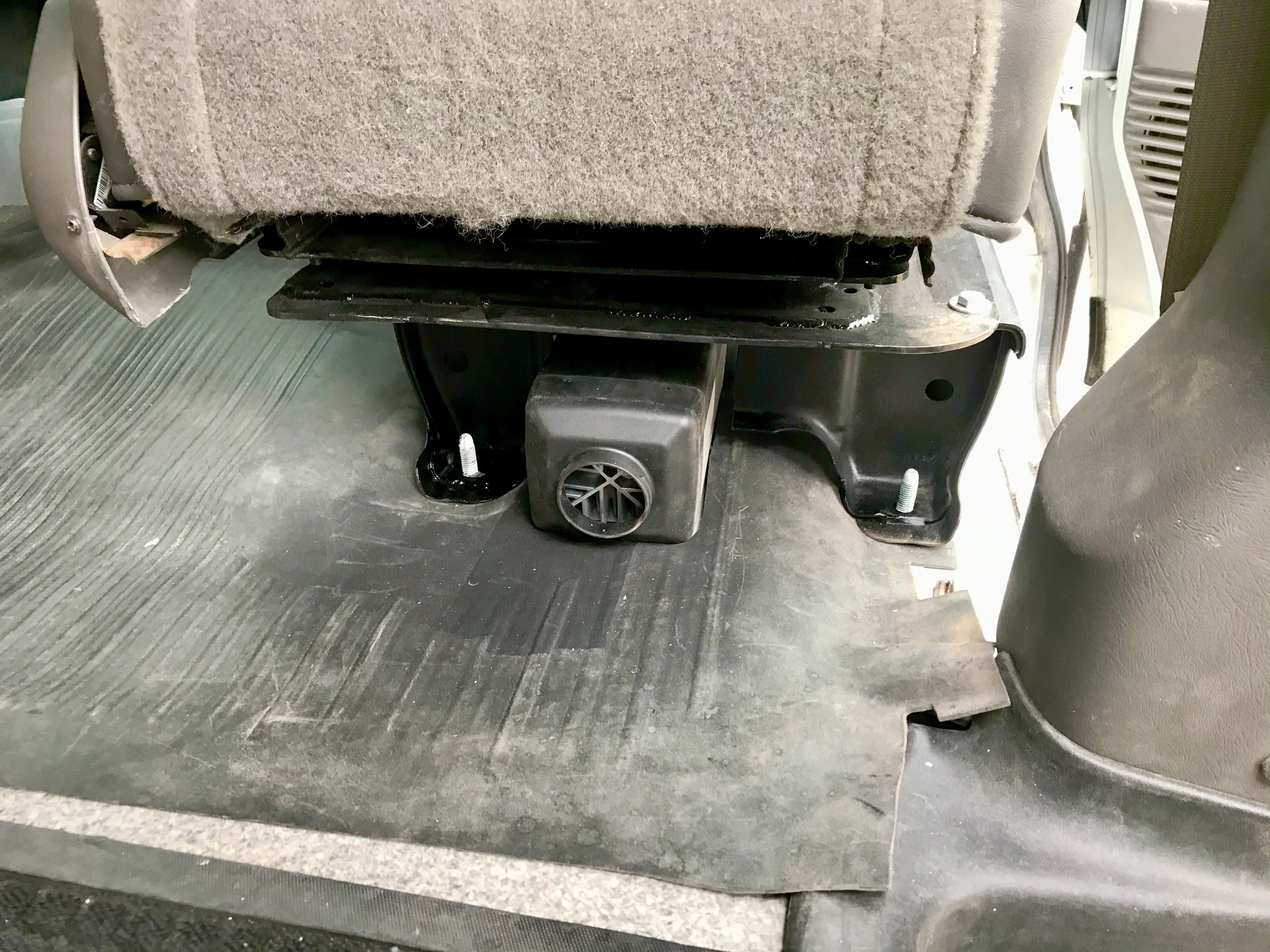
For my install I really wanted the heater under the passenger seat. There’s a few reasons for this. It is semi dead space as it is. We do have a little bin under the seat, but not much else. The access under this area is great as there’s no engine or other components. The only thing under the floor of the van is a heat shield which is easily cut as needed.
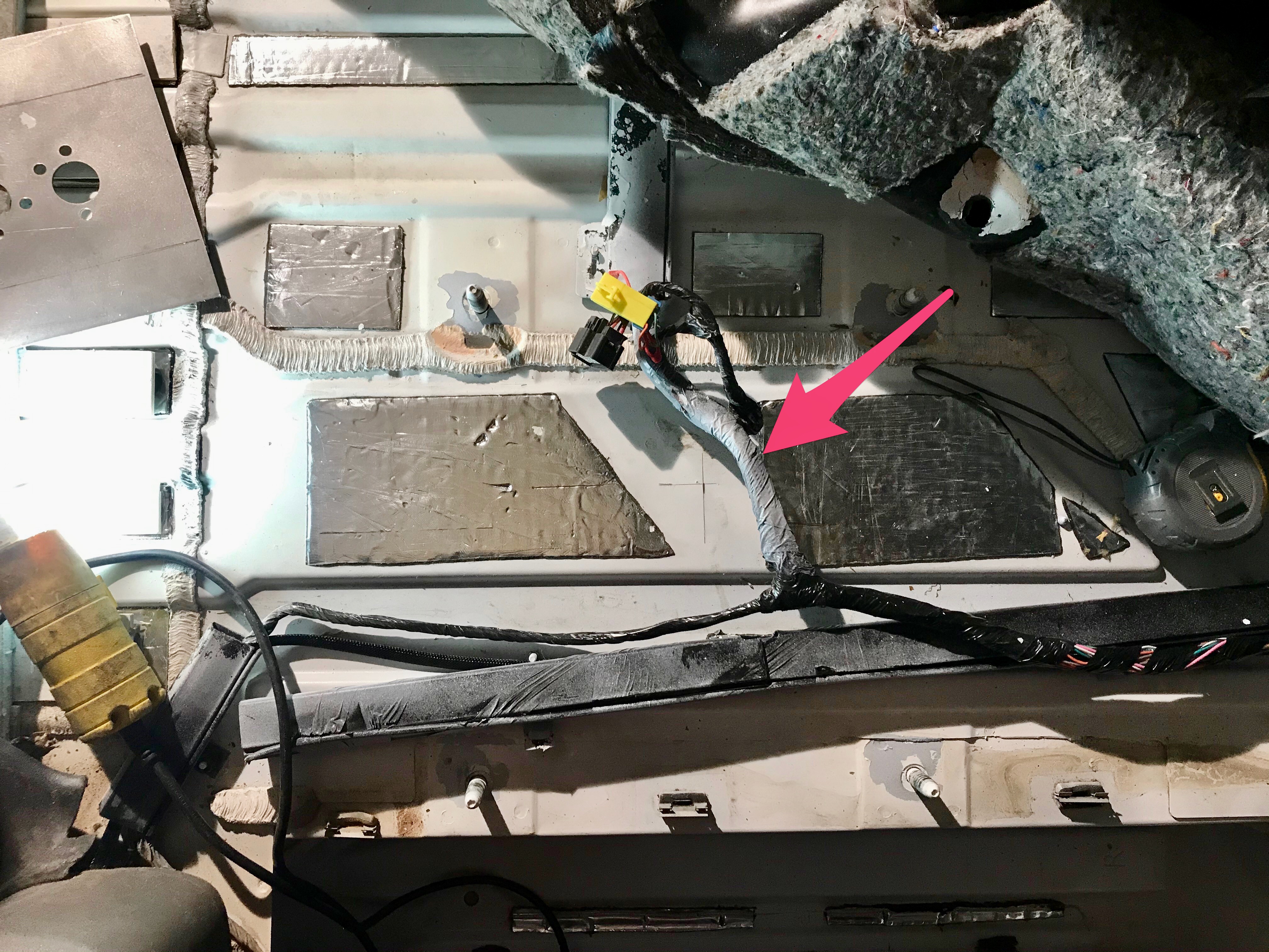
The problem with this location is in order to really tuck the heater under the seat you need a custom seat base. The reason for this is under the floor mat there are two main wire bundles that form a T. There’s one main bundle running longitudinally and a smaller one transversely towards the driver’s seat. These bundles don’t want to move very much because there are wires that are both coming and going in the smaller bundle towards the driver’s side. In order to get around this I needed to mount the heater farther aft than I wanted to. This means that I needed to cut a slot in the seat base to poke the heater out of.
A quick aside on how I rationalized cutting into the seat base. Since this is the seat and therefore a safety component for the person sitting in it, I had reservations of removing a large chunk from the base. Removing it might weaken the base to the point where it doesn’t support the crash loads it would need to. I rationalized that it was OK to do this because I have a swivel seat base attached to the stock base. This swivel seat adds considerable structure and stiffness to the top of the base. Make your own call on this one.
After cutting the slot out you can see that the heater protrudes from the base, but does not extend beyond swivel seat base above.
Fuel Tapping
The install of the unit above is fairly straightforward and anyone who’s already done or doing a van build should be able to handle it. The main difficulty is how to get the heater’s fuel line attached into the vehicle’s fuel system. On most or many of the large vans like Sprinter, Promaster, and Connect, they have auxiliary fuel taps in the head of the fuel pump. Some vans even have an access hatch in the floor of the van to allow getting to the fuel pump without dropping the tank—talk about time savings. This is not the case with a Chevy Express 1500. I checked out a friend’s 2017 Chevy Express 3500 long wheelbase (6.0L engine) which has a Webasto heater installed by Sportsmobile. This van also has an auxiliary fuel port on the fuel pump. I considered the idea of getting this fuel pump and installing it in my van. Unfortunately, the electrical plugs are different, not to mention there could be other differences I’m not aware of.
Webasto’s installation instructions show three ways to tap into the fuel tank. 1) Using a standpipe which is indicated for metal tanks only (came with my kit); 2) Another style standpipe for plastic tanks; 3) Using a ‘T’ that is hooked into the return fuel line. However, if the return line point in the tank is high, you won’t have much fuel accessible for the heater to use. This seems to be the case for the fuel pump on the Express, the return doesn’t extend down into the tank like the normal pick up line. The return line didn’t seem like an option for me so drilling was required.
My kit came with the metal tank fuel standpipe. The Express has a plastic tank so the standpipe specific for that is needed. I found a Webasto technical document showing how to tap the fuel tanks in a number of vehicles. While the document was very helpful in getting ideas, all of the vehicles are European, so nothing specific for a Chevy. What I did lift out of that document is the PN for the plastic fuel tank fuel standpipe (Webasto PN 41S45017A) and how it might be installed into the cap of the fuel pump. Basically many of the installations in that doc show drilling a hole in the cap of the pump and feeding the standpipe down through that. This was much more appealing to me than drilling in the tank itself. While not cheap, replacing a fuel pump is around $200 versus the whole tank if you mess up drilling the tank, not to mention the difficulty of keeping drilling debris out of the tank while drilling.
You gotta drop the fuel tank in order to have access to fuel pump. There’s a video which can help explain this part of it. For an idea on how high to get the van off the ground, I had the frame rail about 18″ off the ground and this was sufficient to access everything. My 2 ton jack stands were sufficient, but I also used a stack of 2x10s under each jack to avoid having to extend the jacks up very much. I used a jack and a buddy to lower the tank. Once the jack was all the way down I used some come-alongs slung under the tank and to any convenient hook point under the van to lower the tank all the way to the ground. The main advantage gained by using the straps and jack is to lower the tank all the way to the ground, thus reducing the height needed to jack the van up.
I’m not going to go into a step by step of details of dropping the tank, but here are some recommendations:
1) Pretty obvious, but have as little fuel in the tank as possible. I had about 1/4 tank and the weight of the tank was manageable with a buddy helping. Don’t count on siphoning to reduce the level, my van had a grill in the filler pipe to prevent this.
2) Have an extra fuel pump on hand before you start. If you do break or crack the original you don’t lose any time to keep moving. Returning the unused one if you don’t need it is worth it in my opinion.
3) Get a lock ring tool! While I was able to get the lock ring off without a tool, getting back on was impossible without the tool. As I didn’t have it on hand I lost two days getting one from Amazon. No local part stores had one in stock at a reasonable price when I checked.
3) Prior to loosening anything get under the van give it a thorough spray down all around the fuel tank with a garden hose. This washes all the surfaces which will be dusty and dirty so you don’t knock stuff in your eyes or in the fuel tank when open. It also may help with disconnecting the electrical plugs. I have a pressure washer but I think a regular hose is a better option because you can direct it in all the nooks and crannies which are hard to access with the pressure gun.
4) The plugs and connectors were a bitch for me. Spray them down well before trying to disconnect and you’ll be in better shape. A significant portion of time dropping the tank was getting connectors unplugged, keep this in mind for your time budget. There aren’t that many connectors, but if they are dirty and stuck like mine you need to take your time unhooking them to prevent breaking them.
5) Get a cheap metric step drill set from Amazon for the cap drilling.
Fuel Pump Drilling
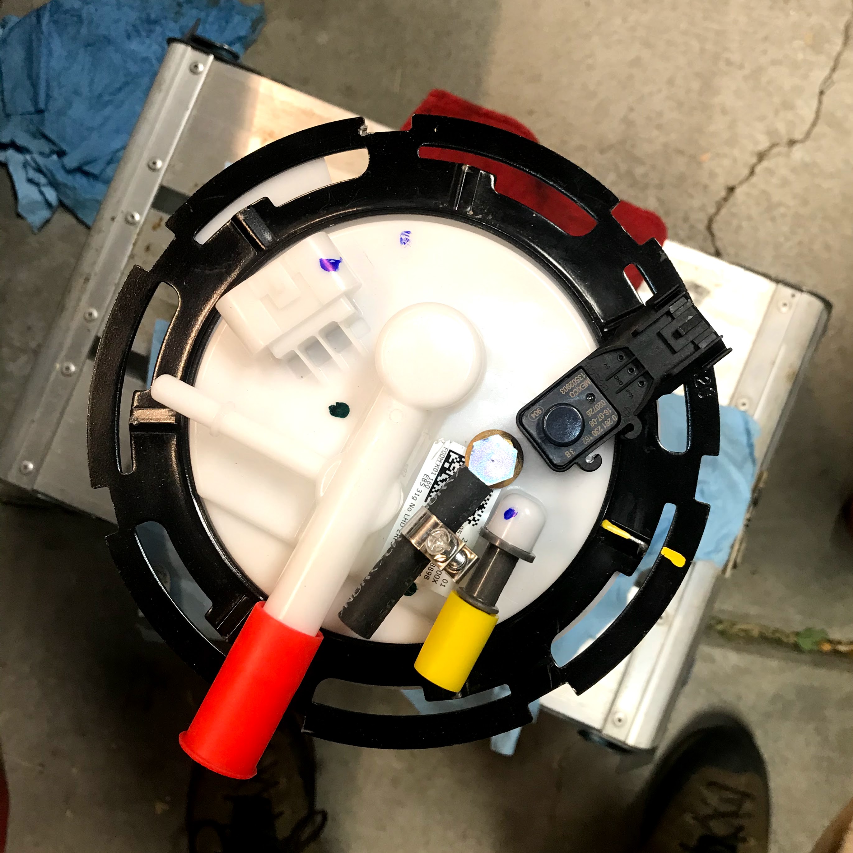
Once the fuel pump is removed you can pick a spot to drill into it to install the heater’s standpipe. The only spot I found was near the rotating electrical connector. This placed the heater’s fuel line in the same direction as the vehicle’s fuel line, not that this has any inherent value that I can guess, but I’m just conveying the idea.
Luckily locating this spot is relatively easy because the fuel pump cap is made from white plastic. By holding the pump up to the light you can see a mark made on the top though the cap. Next up is drilling the cap. Get a sharp center punch and lightly indent the cap to keep the drill from walking. Use a very small drill bit to start, perhaps a 1/16″ or smaller to make the starter hole. Be careful of getting plastic chips into the lower portion of the pump. I used a rag to cover this area and I had a shop vac running with the nozzle just about touching the drill bit. Next step, and this is very important, use a step drill to make the hole for the standpipe. My standpipe hole was 8mm, making a snug fit with the threads of the standpipe. It is likely using a standard fluted drill will crack the pump cap—it did for me. This is where having the extra pump on hand was key. Gently drill the main hole with your step drill and remove any debris as needed.
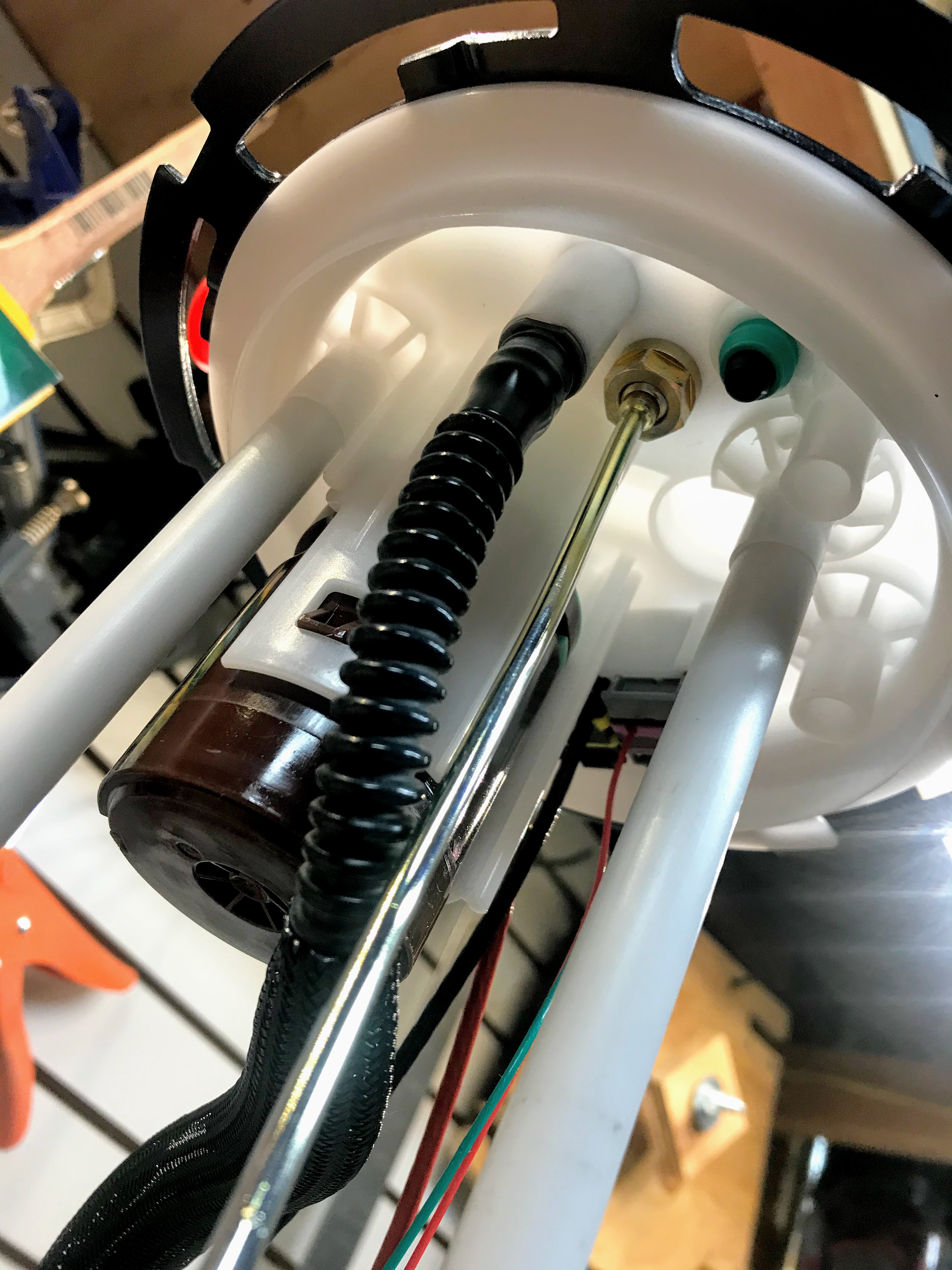
Pick how deep you want the standpipe to go into the the tank and cut it. To do this I measured the depth of the tank from the fuel pump hole and then subtracted about 1″. If you’d like to have more “reserve” fuel for the vehicle that the heater can never use, cut the pipe shorter. Keep in mind the pump assembly is spring loaded so measuring the pipe length off of the pump itself is pointless since it compresses as you push it in the tank. I used a abrasive cut off wheel to cut it. I then used a tiny drill bit to clear out any smeared metal in the hole. I then used a air compressor to blow air from the opposite end to make extra sure there was no debris in the hole.
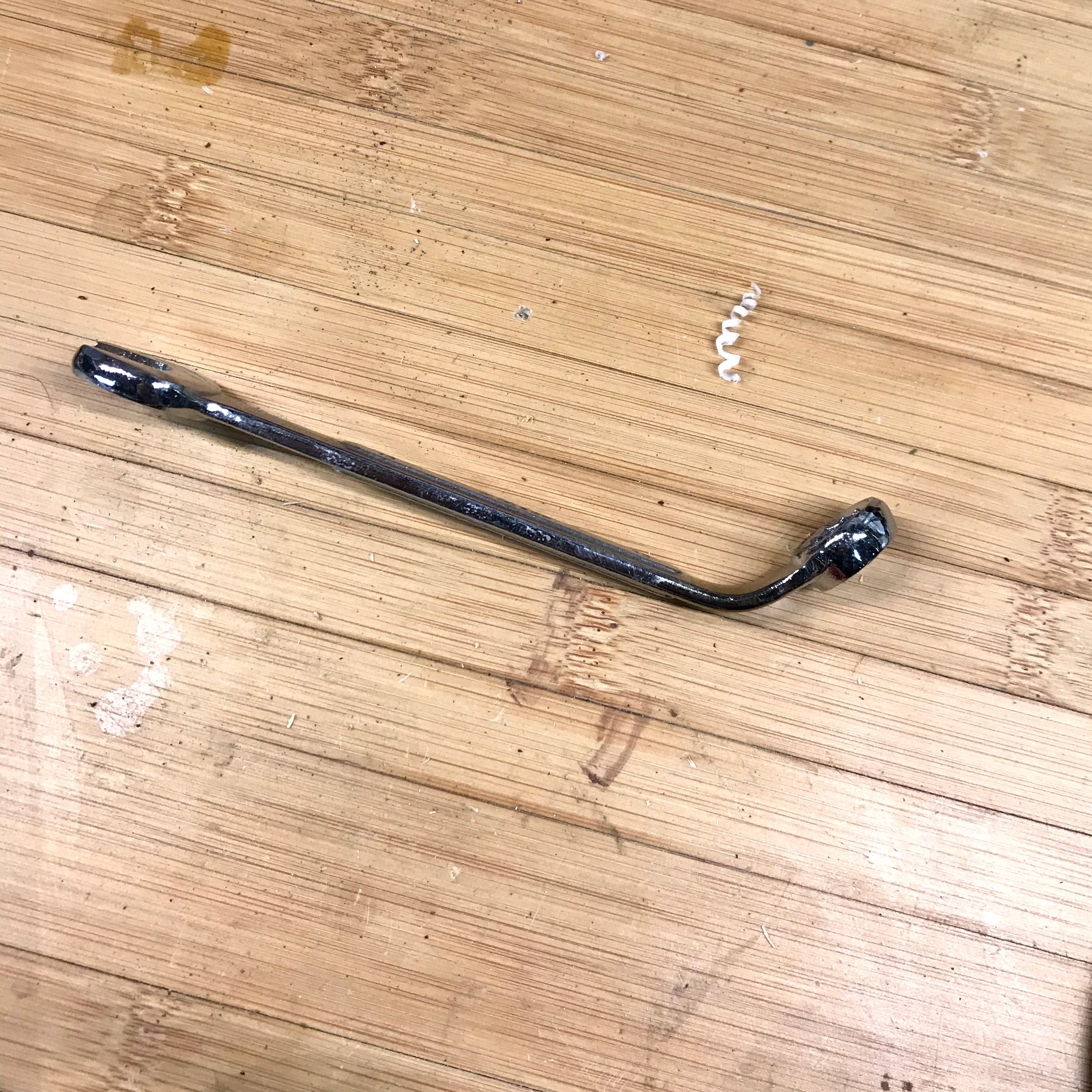
Install the standpipe through the hole and gently bend the standpipe as needed. In order to tighten the bottom nut on the standpipe you’ll need something like a deep right angled box wrench. I did not have something like that on-hand, but I did have a 13mm wrench I didn’t care about so I heated it up and bent it as shown.
After the standpipe is installed reverse all the moves to reinstall.
At the end of it I think the best option is to have mechanic with a lift/pit and familiarity with dropping the tank do that work. If they won’t install the standpipe, get a new fuel pump and install the standpipe yourself. Once that is done you should be able to get any local mechanic to replace the pump with the one you’ve modified. This would save a lot of time and frustration. Getting all the connectors disconnected and slowly lowering the tank was far more time than I anticipated. I would estimate work time from raising the van until the tank was dropped to be about 6 hours. The connectors were a real pain.
Remote Temp Sensor Install
At the recommendation of a friend with one of these heaters, I got the remote temp sensor. In the instructions there is zero mention of a remote temp sensor and how to attach it. After much confusion I looked at the wiring diagrams listed near the end of the install document, make sure to find the correct diagram for your controller. I got the MultiController so my wiring diagram is on page 65. In the wiring diagrams it shows where the internal temp sensor is wired and by extension where the external temp sensor would be hooked in. There’s a resistor across the two wires in the wiring harness that needs to be cut out. Once removed you can wire into those two wires to the plug supplied with the remote temp sensor. It doesn’t matter which wire you hook to what on the external sensor; the two wires from the heater are the same color. I mounted the sensor mid-height in the van, near the bed and not on a surface that conducts temp from the outside. After I installed my sensor I found an update on Far Out Ride with the same instructions for the remote temp sensor.
Other Stuff
If you get the MultiController (recommended) you must perform the unlocking process for the timers. From the factory the controller has up to 21 timers, but only one can be active to run at any time. This renders the MultiController almost pointless. You can however unlock all 21 timers using the process outlined on Far Out Ride. One very important point which wasn’t obvious to me is that this is a two person operation. One person performs the wire short and another person is required to scroll through the menus. Unless you have the service adapter plug there’s no way to do this solo. While in the service menu activate the temperature display on the unit. Again, come on Webasto, just have this one on by default.
Performing the high altitude adjustment is on my list of things to do as recommended on Far Out Ride.
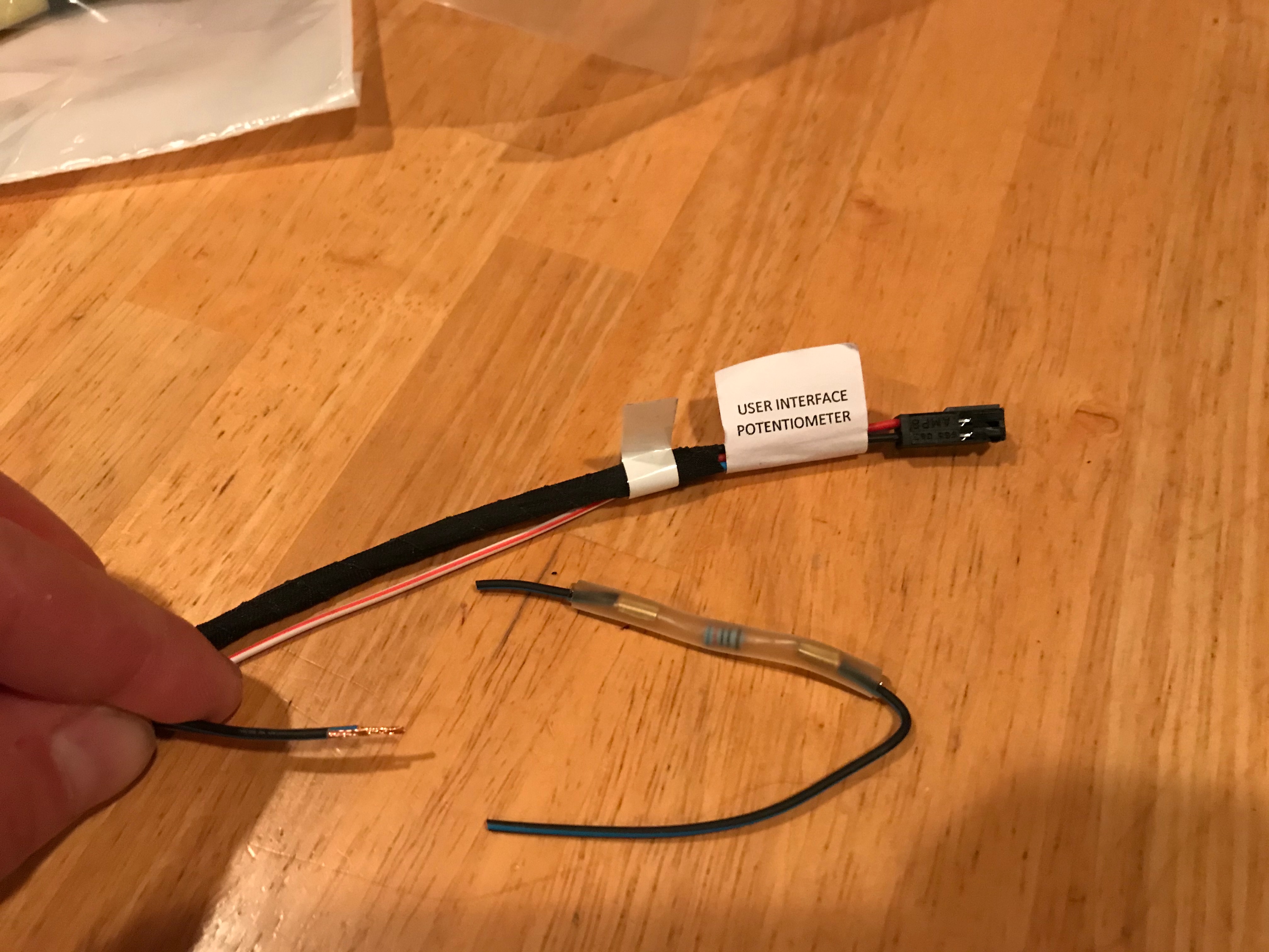
I didn’t like the way the supplied wiring harness was organized. There’s two styles of controler, the rheostat and the MultiController. Those don’t use the same plugs or wires. Unfortunately, Webasto bundles the MultiController with the power wires so those need to be roughly in the same place. The rheostat wires are on their own from the main heater plug (labeled “User Interface/Potentiometer”). In my case I didn’t want the MultiController to be where the power would come from. To remedy this I spent the time, a lot of it, unwrapping the entire wire harness and re-wrapping it so that both controllers’ wire sets were together and the power was separate. This took quite a while and those less patient could achieve the same effect by cutting the wires and supplying their own. I bought some of the fabric tape that Webasto uses and I have to say it is great stuff and wish I’d had some during the main van build for electrical work, it is far superior to standard vinyl tape.
All Build Pictures
Captions can be seen during full screen mode by clicking the ‘i’ in the bottom left corner.


References
https://faroutride.com/air-heater-installation/ – Very great site for many van build topics.
https://www.vanlifeoutfitters.com/installing-webasto-heater-in-camper-van/ – There’s mention on this site that the external temp sensor isn’t compatiable with “newer” Air Top 2000 STC. I can’t speak to the source of this, but the wiring diagrams (p. 65 of instructions) clearly show the option for an external temp sensor, but it does take a little work to do it as I’ve said above.
Webasto Air Top 2000STC Installation Instructions
Webasto MultiControl Instructions – Good for understanding function of the controller and the service menu. Remember you need to ACTIVATE timers after programming them.
Webasto Recommendations for Fuel Extraction on Specific European Vehicles
https://www.heatso.com – I bought my heater from these guys. Incredibly fast non-expedited shipping from the UK to Utah. I had it in my hands 38 hours after ordering it.
https://www.butlertechnik.com – Heatso doesn’t have the plastic fuel tank standpipe so I ordered from these guys. Also quick and reasonable shipping again from the UK.
Fuel Pump Install on Chevy Express Van